All in One View
Content from An Introduction to the Internet of Things
Last updated on 2025-09-06 | Edit this page
Overview
Questions
- What is the Internet of Things?
- How does one connect something to the Internet of Things?
- What is a microcontroller?
- What is an Arduino?
Objectives
- Explain what the Internet of Things is.
- Explain what kind of things can be found on the Internet of Things.
- Explain how things are connected to the Internet of Things.
The Internet of Things
You might hear “Internet of Things” (IoT) and Arduino mentioned together and often those terms are used as if the one implies the other. However, this is not the case. The Internet of Things refers to all kinds of “Things” that have been connected to the Internet. Often, this includes sensing the environment. You can almost think of IoT as the five senses of the Internet.
Before we continue, we should clarify some key terminology used in networking. When two or more computers are connected such that they can communicate it is called a network.
LAN
When computers are connected together as in the below diagram, we call this a “Local Area Network”, or LAN. This is how the computers within a university campus are connected. You may hear this referred to as the institution’s intranet. All the computers inside it can talk to each other, but computers outside the LAN cannot talk to them.

WAN
A LAN is often connected to other telecommunications networks. The network of university networks in the UK is called “Janet”: this allows institutions to talk to each other. This forms a “Wide Area Network” or WAN, as it spans a much larger geographic distance. This network may also be referred to as an internet but is not the same as The Internet.

“The Internet” versus “an internet”
An “internet” (with a lower case i) and “The Internet” (with an upper case I) are different! With an upper case I, The Internet refers to the wide area network that we connect to view web pages such as Google, Amazon etc, or to which we connect to to make Zoom or Skype calls. The Internet is a worldwide collection of networks that we are able to connect to via our Internet Service Providers.
With a lower case i, internet refers to a collection of networks that are connected: a contraction of the phrase “interconnected network”. If university A has a network on campus, and university B has a network, and they decide to connect the two networks as a WAN, then they would have an internet. However they might not necessarily be connected to The Internet.
The Cloud
You may also have heard of The Cloud. The cloud refers to a collection of many, many computers which provide services and resources on the Internet. These machines might be physically located in datacentres all over the globe, but the network between them is designed to be as invisible as possible to you. We often don’t care where the computer running a service in the cloud physically resides, as long as the service is reliable and can be accessed from the Internet.
This ephemerality is why we talk about services as if they are in a “cloud”: the computers and the services they run are like droplets of water floating in the sky. There are also multiple clouds in the “sky”: some operated by technology companies, others smaller, such as private clouds hosted by individual institutions or companies for reasons including cost and security.
Challenge
- What is a network?
- What is an intranet?
- What is the Internet?
- What is the difference between a LAN and a WAN?
- Network: a group of computers connected together. This can be via wires (electrically); microwaves (radio); or fibre optic (light).
- Intranet: a network of computers, such as the one connecting machines within the University to each other.
- The Internet: the network of networks, which connects computers across the globe together.
- A Local Area Network is situated in a small geographic area. A Wide Area Network may span countries, or even the globe. We are even starting to have PANs (Planetary Area Networks)!
Microcontrollers
“So what is this Arduino thing then?”, you may ask. Well, Arduinos are little devices (open-source electronics platform) that were designed to teach people about electronics and they can be used to build electronic circuits that can be connected to the Internet to serve as part of the Internet’s sensing. The main component on an Arduino is a microcontroller which is an “integrated circuit” (or you might know it as a chip) that can be used in conjunction with other electronic components to control things such as motors and sensors. It is, in actual fact, a very small computer and can also be programmed. However, the Arduino is not the only such device, some other popular devices are the ESP32 and ESP8266 boards. To complicate things somewhat, each of these boards come in different flavours - or, at least, different models.
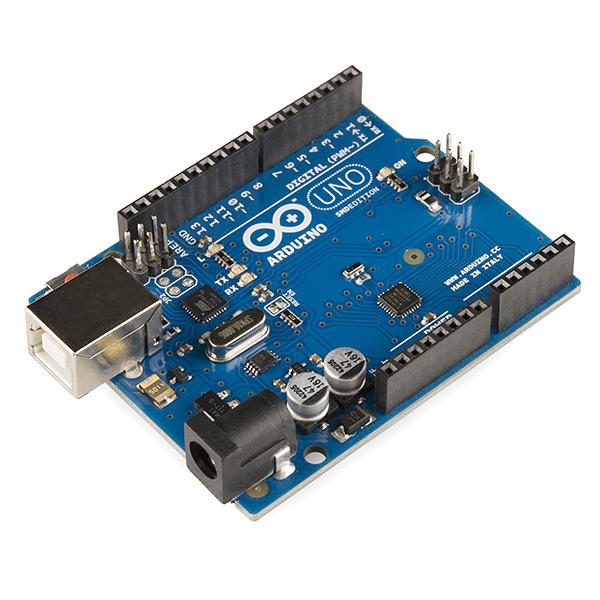
The main thing to notice about the Arduino in the image above is that it has no connectivity to the Internet. So even if we connect sensors to the Arduino it cannot make part of the Internet of Things without being connected to the Internet. However, one can purchase (or build it yourself) a WiFi shield that fits on top of the Arduino and with the shield in place you can program the Arduino to connect to the Internet and publish all the data it retrieves, via the sensors that you connect to it, to the Internet.
Below is an image of the WiFi shield and you might be able to see how its pins allows it to be fitted onto the Arduino Uno.
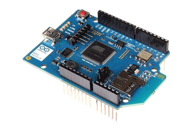
Attribution: oomlout, CC BY-SA 2.0 https://creativecommons.org/licenses/by-sa/2.0, via Wikimedia Commons
There are now several models of Arduinos available, some with onboard WiFi or BlueTooth to allow connectivity to a network. Follow this link to the Arduino site if you would like to see the whole range of Arduino models that are available.
For the purposes of this workshop your instructor might choose to not use an Arduino but rather one of the other options that are available. It doesn’t really matter which one you use because for the projects covered in this lesson, any of them will do. Often, one of the ESP32 or ESP8266 series are chosen because they have onboard WiFi and are also significantly cheaper than Arduinos.
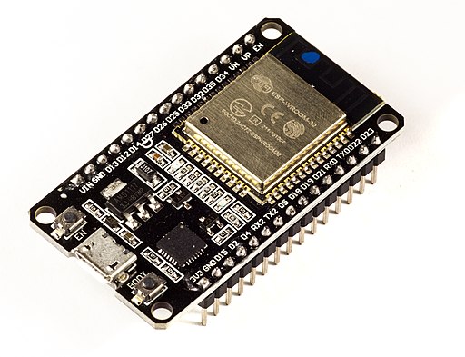
Attribution: Ubahnverleih, CC0, via Wikimedia Commons
The two main requirements for the device selected would be that it is 1) WiFi enabled and 2) can be programmed using the Arduino Integrated Development Environment (IDE). An IDE is just a computer program that provides a programming environment that makes things easier for programmers.
Challenge 1: Which of the following are part of the Internet of things?
With the person next to you, discuss whether you think the following devices are part of the Internet and why? What other devices do you think would make part of the Internet of Things.
- A computer
- An Arduino
- A traffic camera
- A device publishing current temperature to the Internet
- A smart phone
Links:
- Explain the difference between the terms: network, internet, intranet and The Internet
- Identify devices that can be connected to the Internet of Things
- Explain how things can be connected to the Internet of Things.
- Explain what a microcontroller is.
- Explain what an Arduino or and ESP32/8266 is.
Content from The Arduino IDE
Last updated on 2023-07-04 | Edit this page
Overview
Questions
- What is an IDE?
- What is the purpose of the Arduino IDE?
- Which microcontrollers can be programmed with the Arduino IDE?
- How is the Arduino IDE used to program a microcontroller?
- How are microcontroller boards connected to the computer?
- How does the Arduino IDE connect to the microcontroller?
- How would you upload a program?
Objectives
- Explain what an IDE is.
- Explain what the Arduino IDE is used for.
- Identify microcontrollers that can be programmed with the Arduino IDE.
- Run the Arduino IDE.
- Connect the microcontroller board to the computer.
- Connect the microcontroller to the Arduino IDE.
- Enter, compile and upload code.
Introduction
Just like computers, microcontrollers have memory into which we can load programs. To make things easier and to be more productive, programmers have developed software called Integrated Development Environments (IDE). The IDEs provide an editor into which one can type the programming instructions and they usually also make provision for syntax highlighting. Syntax highlighting just means that certain keywords are coloured and that makes it much easier to read. The IDEs also provide ways of uploading code to devices and running the programs. The Arduino IDE was specifically developed for writing programs that uploaded and run on motorcontrollers. Originally it was aimed just at the Arduino but because it is such a convenient environment to work in, it has now been extended to also workwith other microcontrollers.
Running the Arduino IDE
For this episode we have to assume that you were able to successfully install the Arduino IDE and that you are able to start the software from the start menu or the desktop of your computer. When you run the software you will first see the splash window:

After a while the IDE will open. It is actually quite a simple interface. At the top you should see the File, Edit, Sketch, Tools and Help menu items. Just below the menu there are five icons to the left and one on the far right. Below the icons you should see a tab with a filename and a white editing area. Below the editor is a black terminal:
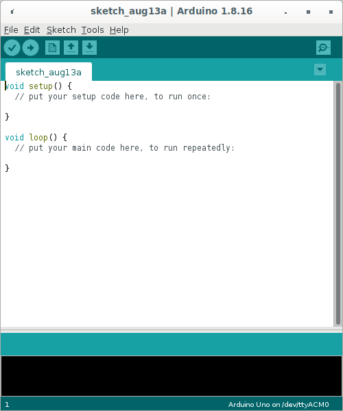
The white area is where you will be typing the code that will be uploaded to the microcontroller. In the black area you will see messages about the compilation of the code and the uploading process. Right at the bottom is a status bar where you will eventually be able to see whether the IDE could connect to your motorcontroller.
The first time you run the IDE the status bar will show the string
Arduino Uno on /dev/ttyAM0 and in the editor you will see
some skeleton code. Note the syntax highlighting:
Configuring the IDE for use with boards other than an Arduino Uno
If you will be using an Arduino or an Arduino compatible device, you don’t have to complete the steps in this section and you can skip to the secion on compiling.
By default the IDE is configured to program an Arduino Uno but we
will be using an ESP32 WROOM 32 board so we first need to configure the
IDE before we can start coding. Start by clicking on the
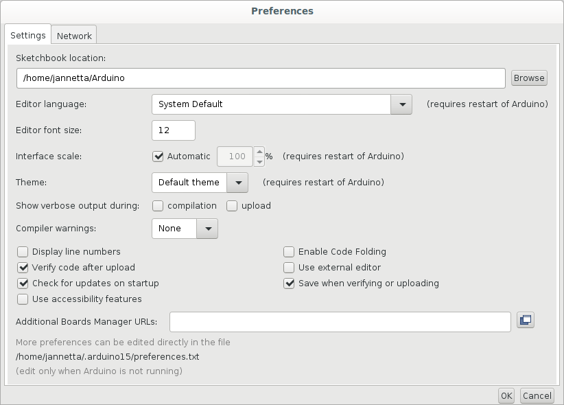
File menu item and then on Preferences.
Towards the bottom of the Preferences window you should find a text area
with the label Additional Boards Manager URLs::
To find the appropriate URL you need to open a web browser and
navigate to:
https://github.com/arduino/Arduino/wiki/Unofficial-list-of-3rd-party-boards-support-urls.
For the ESP32-WROOM-32 you have to find the line that reads:
Espressif ESP32: https://raw.githubusercontent.com/espressif/arduino-esp32/gh-pages/package_esp32_index.json
Copy and paste the address into the text area of the preferences window:
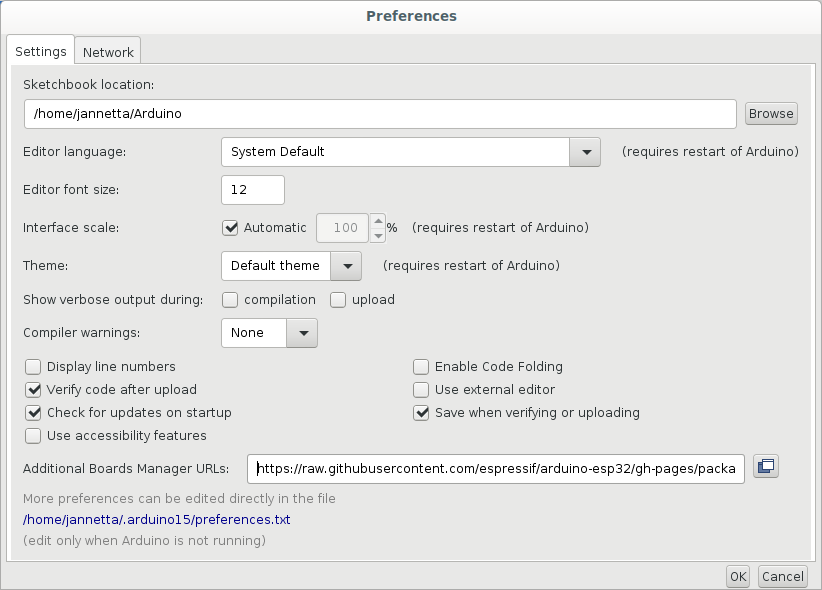
Click on OK
What we have just done is to tell the IDE where to find more information about the ESP32 boards. Because the ESP32 series use a different microcontrollers to the Arduino Uno our programs have to be compiled differently. By default all the Arduino boards are immediately available for selection in the IDE but for other boards we have to give the IDE a place where it can find the information for compiling the code for those other boards.
What is “compiling”?
We have used the term “compiling” a few times now. But what is that?
You’ll notice, that once we start programming, the programming language
uses English words. But, computers do not understand English. Computers
understand only 0 and 1. A compiler takes the human readable programming
language that we entered into the editor and “translates” it into
instructions consisting of 0 and 1 that makes complete sense to the
microcontroller. Although all microcontrollers understand 0 and 1, the
instructions for different microcontrollers differ. The 0s and 1s are
like sounds are to us humans. But different human languages combine the
sounds differently. Similarly the 0s and 1s need to be arranged
differently for microcontrollers designed by different manufacturers or
even different models of microcontrollers manufactured by the same
manufacturer. For this reason we have to tell the IDE which
microcontroller board we are using so that the compiler can translate
our English code into the correct dialect of
microcontroller language.
Selecting the correct board
To select the board you want to compile for click on the
Tools menu item, and then on Board:. On the
dropdown menu, select the microcontroller board that you will be using.
If it is not in the list, click on Boards Manager which is
right at the top. The Boards Manager should pop up.
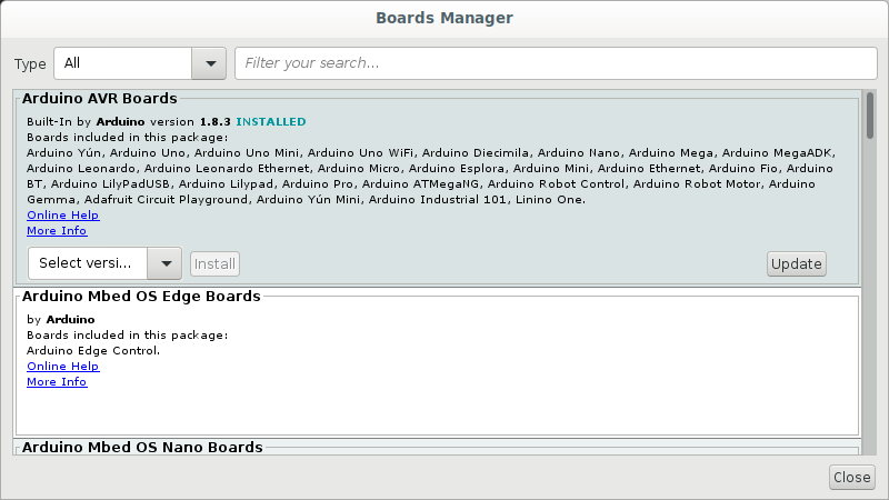
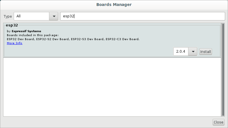
There will be several options available. If you will be using the
ESP32 scroll down to find esp32. You can also type
esp32 in the the text area right at the top of the window and then press
enter. This will then perform a search and you should be able to find
the esp32 option a little quicker. If you hover your mouse over the
esp32 secion, a box with a version and an
Install button should appear. Leave the version, which
should be the latest, as is and click on the Install
button.
When the installation is completed click the Close
button.
If your Arduino is on the list to start with and you don’t need to
install other boards, then just select the board you are using. If you
had to install the esp32 boards, you will have to now click
on the Tools menu option again and then select
Boards. There should now be options for
Arduino AVR boards and ESP Arduino. Select the
ESP option and then select the board you are using which, if you are
using the ESP32 WROOM 32, should be
DOIT ESP32 DevKit V1
Connecting the board to the computer
To connect the motorcontroller board to the computer we need a USB cable. USB cables come in different flavours. You might know this from experience with your mobile/cell phone. The image below shows the names and shapes of the different types of USB connectors:
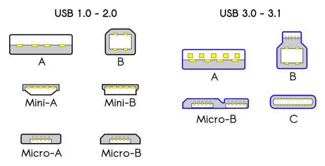
Most computers still have USB type A ports. The latest laptops might have USB C. An Arduino Uno usually has a type B USB port. So for an Uno you will need a cable that has a type A connector on the one side and a type b connector on the other. If your laptop has a type C port you will need type A to type C converter to make the cable fit. An Arduino nano will probably need a type A to type Mini-B cable and an ESP32 will need a type A to Micro-B cable. Chances are that, if you are using devices provided by your host, that they will have the correct cables. Just be aware that if your laptop has a type C port you might need an adapter.
You can now use the cable to connect the motorcontroller board to the computer. Windows computers usually play a sound when you connect a USB device.
Selecting the correct serial port in the IDE
You should now be able to get your Arduino IDE to recognise your
motorcontroller board. In the IDE, click on Tools and then
on Port. You should see at leat one but perhaps more ports listed. Your
IDE might already have selected the port automatically when you
connected the cable. On Windows the devices are usually named COM1,
COM2, COM3 etc. Figuring out which port is being used is sometimes a bit
messy. Your instructor or workshop helpers might be able to assist you
with this.
On Windows it might also be necessary for you to install the serial
drivers required for the ESP32. If you notice the Port item
on the Tools menu is greyed out then this is probably
required. To download the drivers go to:
Select: CP210x Windows Drivers v6.7.6 9/3/2020
When you click on the link it should download a file called
CP210x_Windows_Drivers.zip, to your computer. Right click
and extract the contents from the zip file. There should be two
.exe files extracted. Depending on your computer you have
to double click on one of these to install the driver. If you are not
sure which one to select you can click on the x86 version first. It will
either install or you’ll get a message warning you that your computer
has a 64bit architecture and that you should install the 64bit version.
In that case double click the x64 version to install the driver. After
installation the Port item on the Tools menu
should not be greyed anymore and you should be able to click on it to
select a COM port.
Upload our first sketch
If all went well you should now be able to upload a program to the motorcontroller board. We are going to enter a very simple program just to make sure everything is working. En the editor part of the IDE, modify the code to read as follows:
We’ll go into more detail about programming the motorcontroller in
the next episode. This little program is just for testing. All it is
going to do is to print the word Hello in the
monitor, which we will open after compiling
and uploading the program. To compile and upload press the second button
from the left with the arrow pointing to the right. See the image
below:
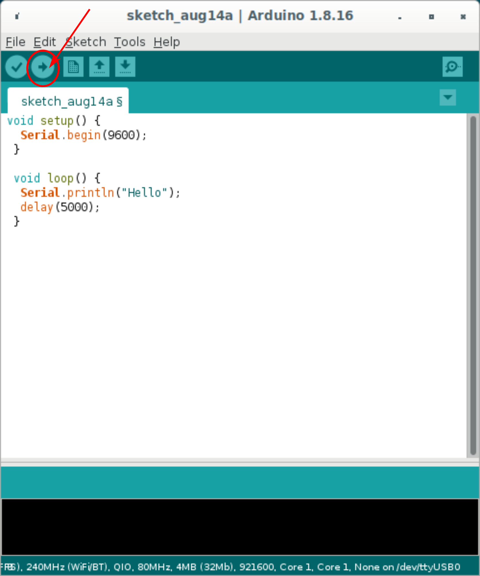
compile and run
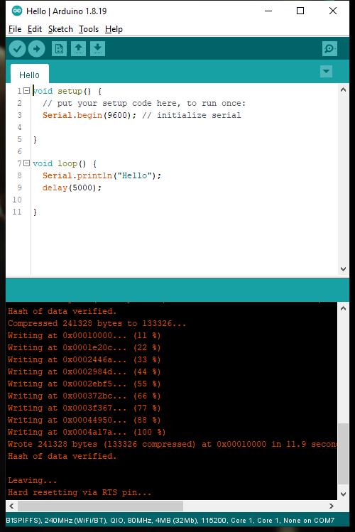
buttonIf all goes well you should see messages displayed in the terminal
section below the editor. The messages should be similar to what is
shown in the image. The progress counter should say (100%),
indicating the all of the compiled code has been uploaded
successfully:
If you are getting an error message similar to this, ``` Connecting……………………………….An error occurred while uploading the sketch .
A fatal error occurred: Failed to connect to ESP32: Wrong boot mode detected (0x13)! The chip needs to be in download mode. For troubleshooting steps visit: https://docs.espressif.com/projects/esptool/en/latest/troubleshooting.html ```
then you might have to download the BOOT button on your
microcontroller board. If you wait for the message to say
Connecting .. and start holding down the button when the
dots appear, the code will suddenly start uploading.
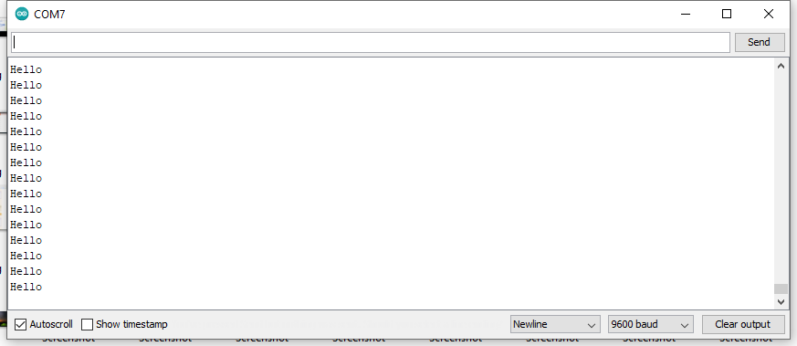
You can now open the serial monitor by clicking first on
Tools and then on Serial Monitor. The word
Hello should now be printed to the monitor every five
seconds.
- Explain what an IDE is.
- Explain what the Arduino IDE is used for.
- Identify microcontrollers that can be programmed with the Arduino IDE.
- Run the Arduino IDE.
- Connect the microcontroller board to the computer.
- Connect the microcontroller to the Arduino IDE.
- Enter code in the editor
- Compile and upload the
- Open the serial monitor
Content from Understanding the code
Last updated on 2023-04-10 | Edit this page
Overview
Questions
- In what language do we program in the Arduino IDE?
- What do the keywords, void, setup and loop do?
- How can we add explanatory comments to the code?
- What is a variable?
- What is a constant?
- What is a function?
Objectives
- Identify the different parts of a sketch
- Explain the purposes of the different parts of a sketch
The language that we use in the Arduino IDE is called
The Arduino Programming Language which is based on a
another programming language called C++. It would have been easy if we
could abbreviate The Arduino Programming Language as APL, but we can’t
because APL refers to a completely different language. The programs
written in the Arduino IDE are also not called programs but rather
sketches.
The language consists of three parts: functions, values (variables and constants), and structures. If you remember the template that was automatically generated when we opened the IDE in the previous episode, you might have recognised some of these parts. All sketches require a setup and a loop as in the following code snippet:
C
void setup() {
  // put your setup code here, to run once:

}

void loop() {
  // put your main code here, to run repeatedly:

}You can find more information about functions, values and structures in the online reference manual at https://www.arduino.cc/reference/en/.
- The keywords
voidandintare the return types. If a function does not have a value to return, the keywordvoidis used.intmeans that the function returns a value that is an integer. You can find a list of all thedata typesthat can be return on the Language Reference website - The words
setup,loopandgetMagicNumberare the names of the functions. - The names of the functions are followed by parenthesis. We will see later on how they are used.
- The curly brackets indicate the beginning and end of the function.
The left curly bracket should appear after the parenthesis. The
following lines are instructions that the micocontroller has to execute.
The right curly bracket closes the function and indicates that the end
has been reached. If the function does not have a return type of
void, i.e. it has any of the other data type, then the last line in the function has to contain the keywordreturnfollowed by a value (or a variable containing a value) of the specified return type.
Functions
All functions have the following:
- a return value type
- a unique name
- parenthesis
- curly brackets
All sketches must have a setup and a loop function.
Any instructions that we put in the setup will be executed
when the program starts. After completing the instructions in setup the
microcontroller continues to the loop function where the
microcontroller will execute all the instruction over and over again -
in an infinite loop. As in the example, there can be other functions.
Such functions are created as needed and can be called from any other
function. Functions can even call themselves. There are many built-in
functions, some of which we will be using. It is also possible to load
libraries that will give us even more functions for more
functionality. We will also be using some of those in this lesson.
Variables and Constants
Variables and constants are named memory positions in the
motorcontroller in which one can store a value. The value of variables
can be changed but the values of constants cannot be changed after they
have been allocated a value for the first time. Before a value can be
assigned to a variable, the variable has to be declared. The declaration
tells the compiler of what type of value will be stored in
the variable.
An example sketch
Let’s start by creating a new sketch to experiment with the things we
have mentioned so far. We will also introduce one
structure, the for-loop. On the menu click
File and then New. When you create a new
sketch, the IDE will automatically add the setup and loop functions for
you. There will be no code in the functions, just two comments. Comment
lines start with // and are ignored by the compiler but
allows the programmer to enter comments to document what the program
does. Do use the comment feature. It makes it much easier when you come
back to the code or when you have to pass the code onto someone
else:
C
// This program will print numbers starting at the value allocated to the
// variable `minimum` up to the variable called `maximum`

// declare a constant of type integer called minimum
const int minimum = 0;

// declare a constant of type integer called maximum
const int maximum = 100;

// delcare a variable of type float called pi
// a float type is a number that a decimal point.
float pi = 3.14159265358979;

void setup() {
  // Initialise the `Serial` library and tell it what speed to
  // use for communication with the computer via the USB port
  // The Serial library is included in the language by default
  // so we don't have to import it.
  Serial.begin(9600);
}

void loop() {
  // Use a loop structure to count from minimum to maximum
  // Notice the `int i` variable that is used as the counter
  // To understand the for-loop structure, read it as:
  // For i equals minimum to i less-than-or-equal-to maximum,
  // increment i by one (the ++ means increment by 1)

  for (int i = minimum; i <= maximum; i++) {

    // create a new value called multiply_pi and allocate
    // the value of `i * pi` to it

    float multiply_pi = i * pi;

    // Use the print function in the Serial library to
    // print `i` to the Serial Monitor
    Serial.println(multiply_pi);
  }

  // create a delay of 5000 milliseconds (5 seconds)
  delay(5000);
  // After the delay the microcontroller will start at the
  // beginning of loop() and run all the code inside it again.
}
Challenge 2:
With the person next to you, can you do the following?
- Identify variables, constants, functions and structures
- Of what types are the variables and constants?
- Explain what the code is doing
What does the code do?
- Firstly we declare two constants of type integer,
minimumandmaximumand we give them values of 0 and 100. - We declare on variable of type float called
piand we give it a value of 3.14159265358979. - The code will first enter the
setup()function and, - initialise the serial communications from the ESP to the computer at a speed of 9600 baud. Baud is the data transmission rate in bits per second.
- Next the code will enter the loop function.
- Inside the loop function we create another loop with the for-loop
structure. This loop will use the variable
iwhich will be of typeintegerand it will start withiequal tominimum. It will then incrementiby one for each iteration of the loop whileiis less thanmaximum, until it becomes equal tomaximum. - On each iteration of loop a variable of type float is declared that
is called
multiply_pi. -
multiply_pi' is given the value of whateveriis at the time multiplied bypi`. - The current value of
multiply_piis then sent and printed in the serial monitor - When
ireaches the valuemaximum, the loop will terminate and the program will pause for 5000 milliseconds. - Because this happens in the
loop()function the whole process will start all over again and this will go on indefinitely
https://www.arduino.cc/reference/en/
- Identify variables, constants, functions and structures
- Know how to identify a function
- Recognise the different types of values that variables and constants can have and what type of information each of these can hold.
- Know where to find the Arduino Programming Language reference
Content from Connecting the first sensor
Last updated on 2022-09-12 | Edit this page
Overview
Questions
- Can you identify a DHT11 and DHT22 temperature/humidity sensor?
- Can you identify the pins on the DHT sensor?
- Can you identify the pins on the ESP that we will need to use?
- Can you explain what the code will do?
Objectives
- Connect a DHT11 or DHT22 to the microcontroller using a breadboard and connectors
- Write the code required to read the temperature and print it to the serial monitor
Connecting the temperature sensor
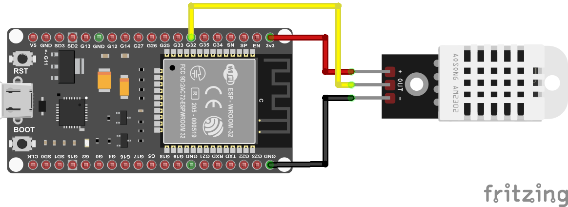
The sensor that we will be using is a DHT11 or a DHT22. The easiest is to use a “module” which is the sensor soldered to a little circuit board. The circuit board includes a resistor which is a tiny component that you might be able to see on the board. If you don’t have the module, but you have the sensor, then you need to obtain a 10K Ohm resister. The first diagram below show how to wire up the module. The second diagram shows how to wire up the sensor using a resistor.

Before entering our code we need to install a special library that is required for the temperature sensor. Without the library the code that we will need to write to get the sensor to work will be much more complicated. Fortunately there are many people around the world the write the difficult code and make it available as libraries for us to make our lives easier.
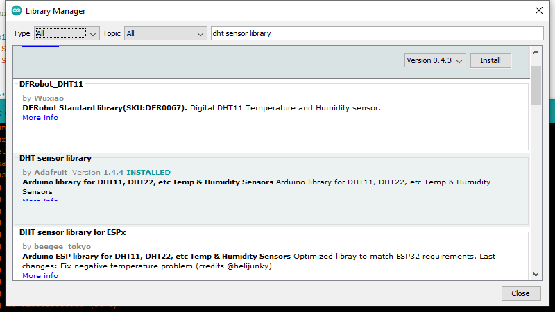
To install the library click on the Tools menu item and
then select Manage libraries.... The Library Manager window
should pop up. In the text field type dht sensor library
and press enter to search for the library. Look for the entry
“DHT sensor library by Adafruit” and
then click on the Install button.
Close the library manager by clicking on the Close
button. Next we want to create a new sketch. Click on File
and then New. A new instance of the Arduino IDE should
open. You can now enter the code below in the editor
C
#include <DHT.h>

#define DHT_SENSOR_TYPE DHT22
#define DHT_SENSOR_PIN 32 // ESP32 pin connected to DHT sensor

const int readingdelay = 3000;

DHT dht_sensor(DHT_SENSOR_PIN, DHT_SENSOR_TYPE);

void setup() {
  Serial.begin(9600); // initialize serial
  Serial.println(F("Starting ..."));
  dht_sensor.begin(); // initialize the DHT sensor
}

void loop() {

  float temperature = dht_sensor.readTemperature();   // read temperature in Celsius


  if (isnan(temperature)) {
    Serial.println("Failed to read from DHT sensor!");
  } else {
    char tempString[8];
    dtostrf(temperature, 1, 2, tempString);
    Serial.print("Temperature: ");
    Serial.println(temperature);
  }

  // wait a 3 seconds between readings
  delay(readingdelay);
}
Once you have entered the code you can press the Upload
button again. The code should compile and then upload to the
microcontroller board. Don’t forget to press and hold down the
BOOT button until the uploading starts.
Explanation of the code
- Identified the DHT11/22 humidity and temperature sensor
- Identified the three pins on the sensor
- Identified the three required pins on the ESP32
- Connected the DHT sensor to the ESP32
- Added the required code to the Arduino IDE to read the temperature from the sensor and display it in the serial monitor.
Content from Connecting the second sensor
Last updated on 2023-04-10 | Edit this page
Overview
Questions
- Question
Objectives
- Objective
Connecting a light level sensor
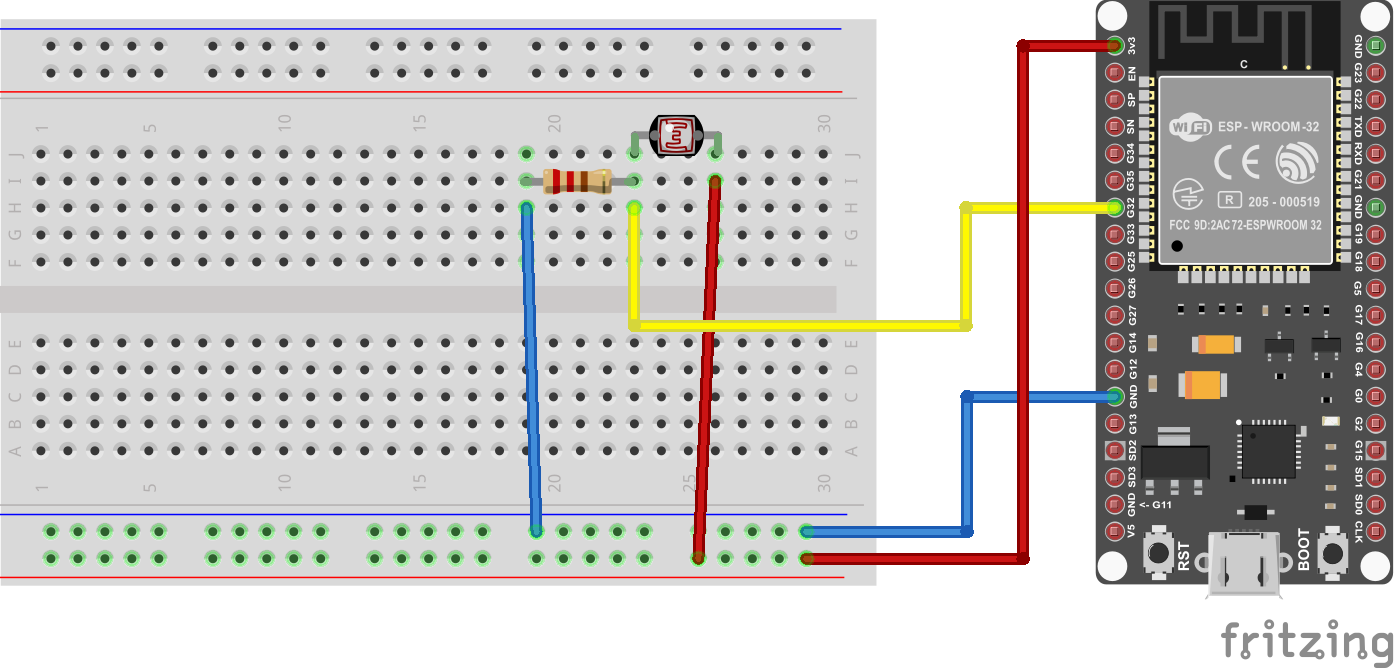
ToDo
Explain how to connect the resistors according to image below
C
#define LIGHT_SENSOR_PIN 32 // ESP32 pin GIOP36 (ADC0)

const int readingdelay = 3000;

void setup() {
  Serial.begin(9600); // initialize serial
  Serial.println(F("Starting ..."));
}

void loop() {

  int lightlevel = analogRead(LIGHT_SENSOR_PIN);     // read light level
  Serial.print("Light: ");
  Serial.println(lightlevel);

  // wait a 3 seconds between readings
  delay(readingdelay);
}
Explanation of the code
- Keypoint
Content from Combining the two circuits
Last updated on 2022-08-27 | Edit this page
Overview
Questions
Objectives
- Combining the two circuits
- Combine the code for the two circuits
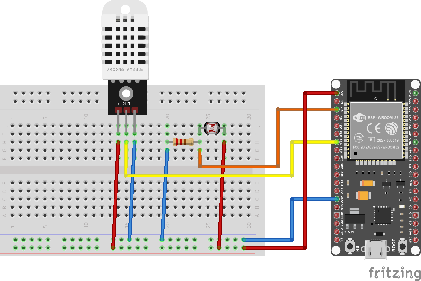
Combine the two circuits on one breadboard
Combine the code for the two circuits
C
#include <DHT.h>
#include <WiFi.h>

#define DHT_SENSOR_TYPE DHT22
#define DHT_SENSOR_PIN 32 // ESP32 pin connected to DHT sensor
#define LIGHT_SENSOR_PIN 36 // ESP32 pin GIOP36 (ADC0)

const int readingdelay = 3000;


DHT dht_sensor(DHT_SENSOR_PIN, DHT_SENSOR_TYPE);

void setup() {
  Serial.begin(9600); // initialize serial
  Serial.println(F("Starting ..."));
  dht_sensor.begin(); // initialize the DHT sensor
}

void loop() {

  float temperature = dht_sensor.readTemperature();   // read temperature in Celsius
  int lightlevel = analogRead(LIGHT_SENSOR_PIN);     // read light level


  if (isnan(temperature)) {

    Serial.println("Failed to read from DHT sensor!");

  } else {
    /* When reading the temperature and light levels, we get the values
       as numbers, but when we send it to the MQTT broker the values
       have to be converted to strings. We therefore have to declare
       variables of type char into which the number values can be transferred
    */
    char tempString[8];
    char lightString[8];

    // Print the temperature to the monitor
    Serial.print("Temperature: ");
    Serial.println(temperature);

    // Print the light level to the monitor
    Serial.print("Light: ");
    Serial.println(lightlevel);

    // wait a 3 seconds between readings
    delay(readingdelay);
  }
}
Explain the code
- Keypoint
Content from Using MQTT for the Internet of Things
Last updated on 2022-08-30 | Edit this page
Overview
Questions
- What is MQTT?
- How does MQTT work?
- What is an MQTT publisher?
- What is an MQTT broker?
- What is an MQTT subscriber?
- What is a client?
- What is a server?
Objectives
- Explain how MQTT works
Adding MQTT to our sketch
What is MQTT?
Message Queuing Telemetry Transport
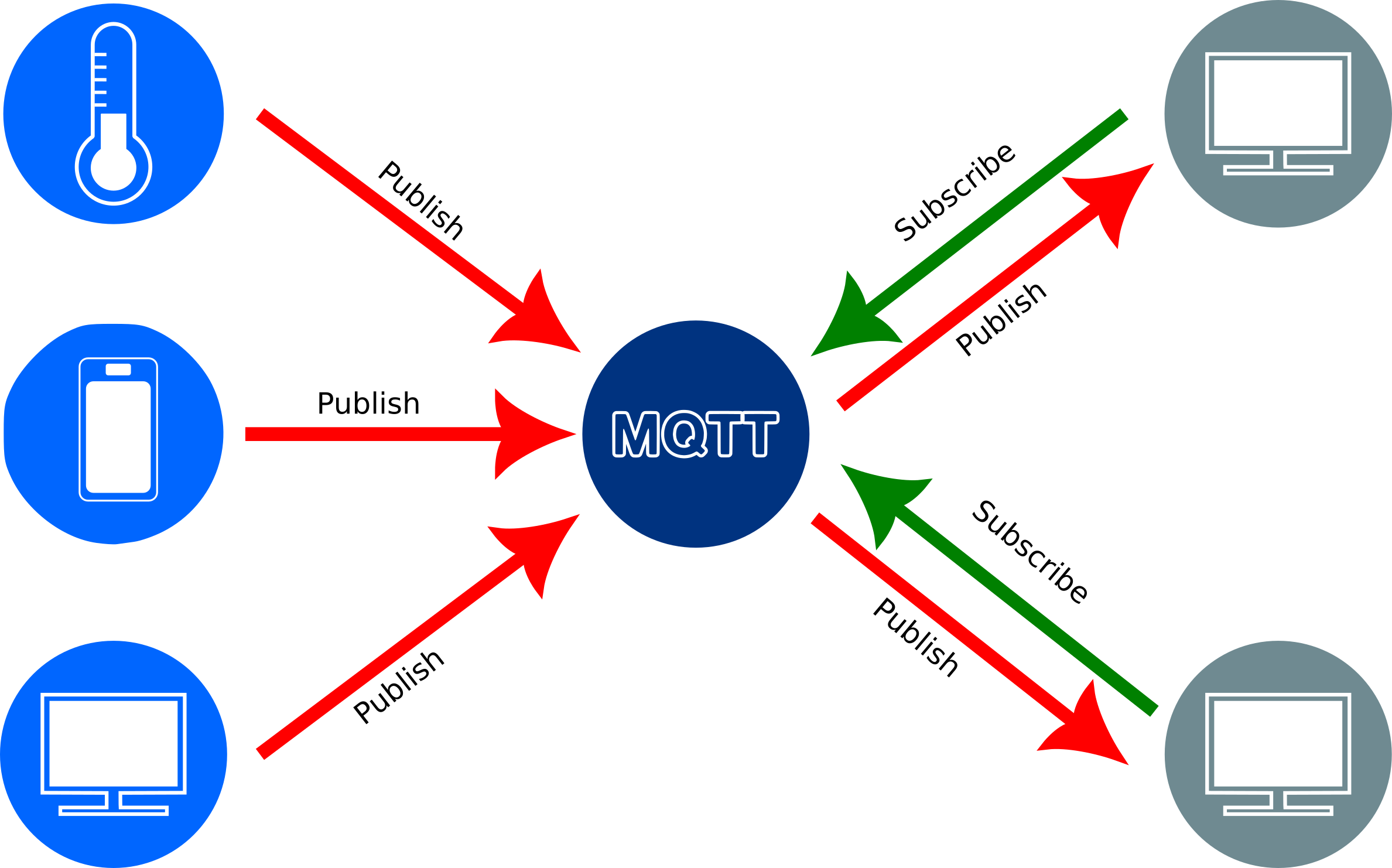
MQTT (originally an initialism of MQ Telemetry Transport[a]) is a lightweight, publish-subscribe, machine to machine network protocol. It is designed for connections with remote locations that have devices with resource constraints or limited network bandwidth.
There are three components to the MQTT architecture, publishers, subscribers and a broker. Publishers are devices on the Internet of Things that publish messages with a specific topic to a broker. Subscribers subscribe to specific topics on the broker. When a new value for a specific topic is published by a publisher, then all the subscribers to that topic will receive it.
Challenge
Discuss, with the person next to you the following:
- What kind of devices we are likely to find on the Internet of things?
- Who would typically publish information from such devices?
- Who would typically subscribe to the data?
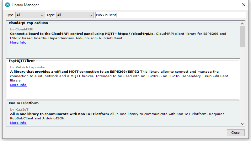
Importing the MQTT library into the Arduino IDE
To be able to enable MQTT functionality we need to add yet another
library to our Arduino IDE. As before select Tools on the
menu and then Manage Libraries. Enter
PubSubClient into the text box for searching. Scroll down
until you find PubSubClient by Nick O'Leary and click the
Install button:
There are three pieces of information that we will need before we enter the code for sending and messages via MQTT:
- The
ssidof your Internet access point - The password for the access point
- The IP address or hostname of your MQTT broker
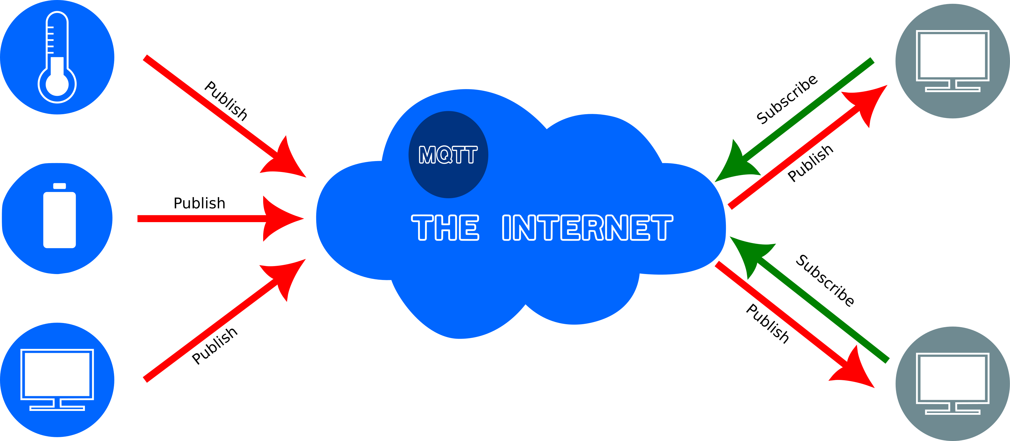
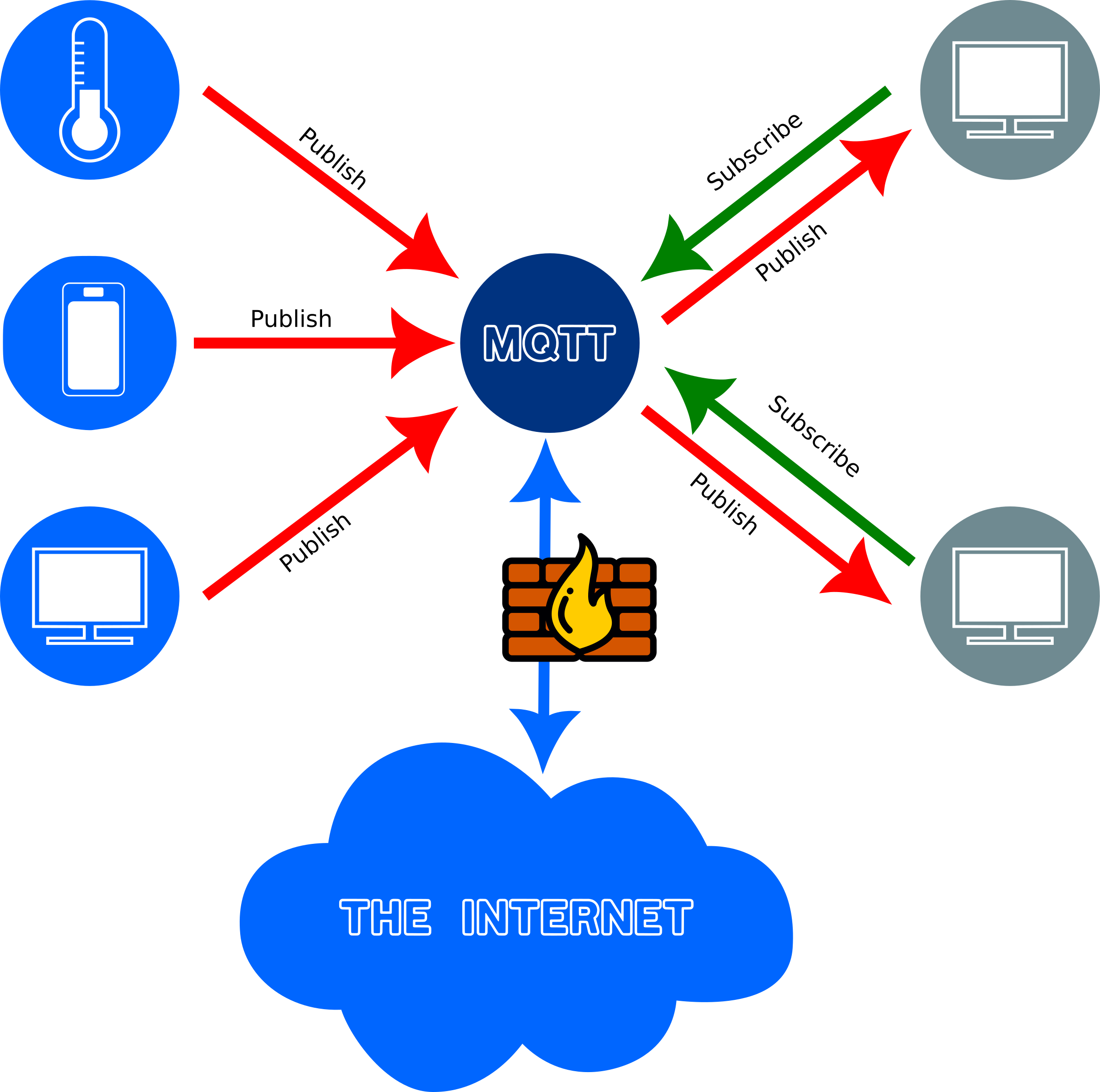
There are several free MQTT servers available on the Internet. Alternatively one can set up one’s own server running an MQTT broker. In the diagrams below two alternative setups are shown. In the first case there is an MQTT server on the Internet that devices can publish or subscribe to. In the second case a local MQTT broker is used which has the advantages that all network traffic can be private, it doesn’t have to be shared to the Internet. For the purposes of this workshop for instance we might want to set up our own server so that we are not dependent on the Internet.
In the sketch below you will have to replace the values assigned to
the variables ssid, password and
mqtt_server. Your instructor should provide you with the
appropriate values which will depend on the MQTT broker you are going to
use.
For now we will continue as if your instructor has set up a local network that includes an access point to which your computer has to connect and an MQTT broker. You might, or might not, be connected to the Internet once you connect to the access point, but that won’t matter.
C
#include <DHT.h>
#include <WiFi.h>
#include <PubSubClient.h>

#define DHT_SENSOR_TYPE DHT22
#define DHT_SENSOR_PIN 32 // ESP32 pin connected to DHT sensor
#define LIGHT_SENSOR_PIN 36 // ESP32 pin GIOP36 (ADC0)

const int readingdelay = 3000;
const char* ssid = "raspi-webgui";
const char* password = "ChangeMe";
const char* mqtt_server = "192.168.0.1";
const String your_name = "/JohnSmith";

DHT dht_sensor(DHT_SENSOR_PIN, DHT_SENSOR_TYPE);
WiFiClient espClient;
PubSubClient client(espClient);

String topic_temperature = your_name + "/dht22/temperature";
String topic_light = your_name + "/ldr/light/";

void setup() {
  Serial.begin(9600); // initialize serial
  Serial.println(F("Starting ..."));
  dht_sensor.begin(); // initialize the DHT sensor
  setup_wifi();
  client.setServer(mqtt_server, 1883);
  client.setCallback(callback);
}

void loop() {
  if (!client.connected()) {
    reconnect();
  }
  client.loop();

  float temperature = dht_sensor.readTemperature();   // read temperature in Celsius
  int lightlevel = analogRead(LIGHT_SENSOR_PIN);     // read light level


  if (isnan(temperature)) {

    Serial.println("Failed to read from DHT sensor!");

  } else {
    /* When reading the temperature and light levels, we get the values
       as numbers, but when we send it to the MQTT broker the values
       have to be converted to strings. We therefore have to declare
       variables of type char into which the number values can be transferred
    */
    char tempString[8];
    char lightString[8];

    /**
     * Transfer the number values into strings
     */
    dtostrf(temperature, 1, 2, tempString);
    dtostrf(lightlevel, 1, 2, lightString);

    // Print the temperature to the monitor
    Serial.print("Temperature: ");
    Serial.println(temperature);
    // Publish the temperature to the MQTT broker
    publishMQTT(topic_temperature, tempString);

    // Print the light level to the monitor
    Serial.print("Light: ");
    Serial.println(lightlevel);
    // Publish the light level to the MQTT broker
    publishMQTT(topic_light, lightString);

    // wait a 3 seconds between readings
    delay(readingdelay);
  }
}

void setup_wifi() {
  delay(10);
  // We start by connecting to a WiFi network
  Serial.println();
  Serial.print("Connecting to ");
  Serial.println(ssid);

  WiFi.begin(ssid, password);

  while (WiFi.status() != WL_CONNECTED) {
    delay(500);
    Serial.print(".");
  }

  Serial.println("");
  Serial.println("WiFi connected");
  Serial.println("IP address: ");
  Serial.println(WiFi.localIP());
}

void callback(char* topic, byte * message, unsigned int length) {
  Serial.print("Message arrived on topic: ");
  Serial.print(topic);
  Serial.print(". Message: ");
  String messageTemp;

  for (int i = 0; i < length; i++) {
    Serial.print((char)message[i]);
    messageTemp += (char)message[i];
  }
  Serial.println();
}

void reconnect() {
  // Loop until we're reconnected
  while (!client.connected()) {
    // Create a random client ID
    String clientId = "ESP32Client-";
    clientId += String(random(0xffff), HEX);
    Serial.print(clientId + " attempting MQTT connection...");
    // Attempt to connect
    if (client.connect(clientId.c_str(), "jannetta", "f0r3v3rl1n8x")) {
      Serial.println("connected");
    } else {
      Serial.print("failed, rc=");
      Serial.print(client.state());
      Serial.println(" try again in 5 seconds");
      // Wait 5 seconds before retrying
      delay(500);
    }
  }
}

void publishMQTT(String topicString, char payload[8]) {
  unsigned int length = topicString.length() + 1;
  char topic[length];
  topicString.toCharArray(topic, length);
  Serial.print(topic);
  Serial.print(": ");
  Serial.println(payload);
  client.publish(topic, payload, true);
}

String byteArrayToString(byte * byteArray, unsigned int length) {
  String messageTemp;
  for (int i = 0; i < length; i++) {
    messageTemp += (char)byteArray[i];
  }
  return messageTemp;
}Explanation of the code
- Keypoint
Content from Subscribing to an MQTT topic
Last updated on 2022-08-30 | Edit this page
Overview
Questions
- What does one need to get the information published by sensors on the IoT?
- What is meant by “topic” in terms of MQTT?
- How can I save the published data to file?
Objectives
- Connecting to an MQTT broker
- Subscribing to topics
- Export data to a file
Our current status
In the previous episodes we have:
- Added the URL in the IDE’s preferences to detect the configurations for the ESP32 board
- Installed the library required for the DHT sensors
- Connected a DHT11 or DHT22 sensor to an ESP32 microcontroller board
- Entered the code in a sketch to get temperature readings from the DHT sesions
- Connected a Light Dependent Resistor to the same ESP32 microcontroller board
- Entered the code in a sketch to get light level readings from the LDR
- Entered the code in the sketch to connect to our local network and publish the sensor readings to an MQTT broker
Subscribing to an MQTT topic
At this point your ESP microcontroller board should have a temperature and a light level sensor on it. It should have connected to your local network and to an MQTT broker and it is publishing the readings to a topic to the MQTT broker.
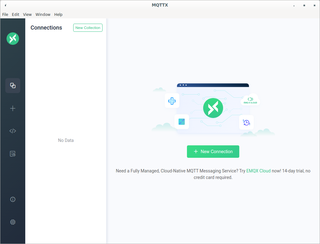
We now need client software to connect to the MQTT broker and subscribe to the topic to which your sensor readings are published. There are quite a few clients available as well as libraries for several programming languages including Python. For this lesson we are going to use MQTTX, a cross platform, open source application. Hopefully you were able to install MQTTX as descripted on the setup page.
Let’s start by running MQTTX. If it is the first time you are running it, a window similar to the image below should open:
Click on the green + New Connection button and then
following window should appear:
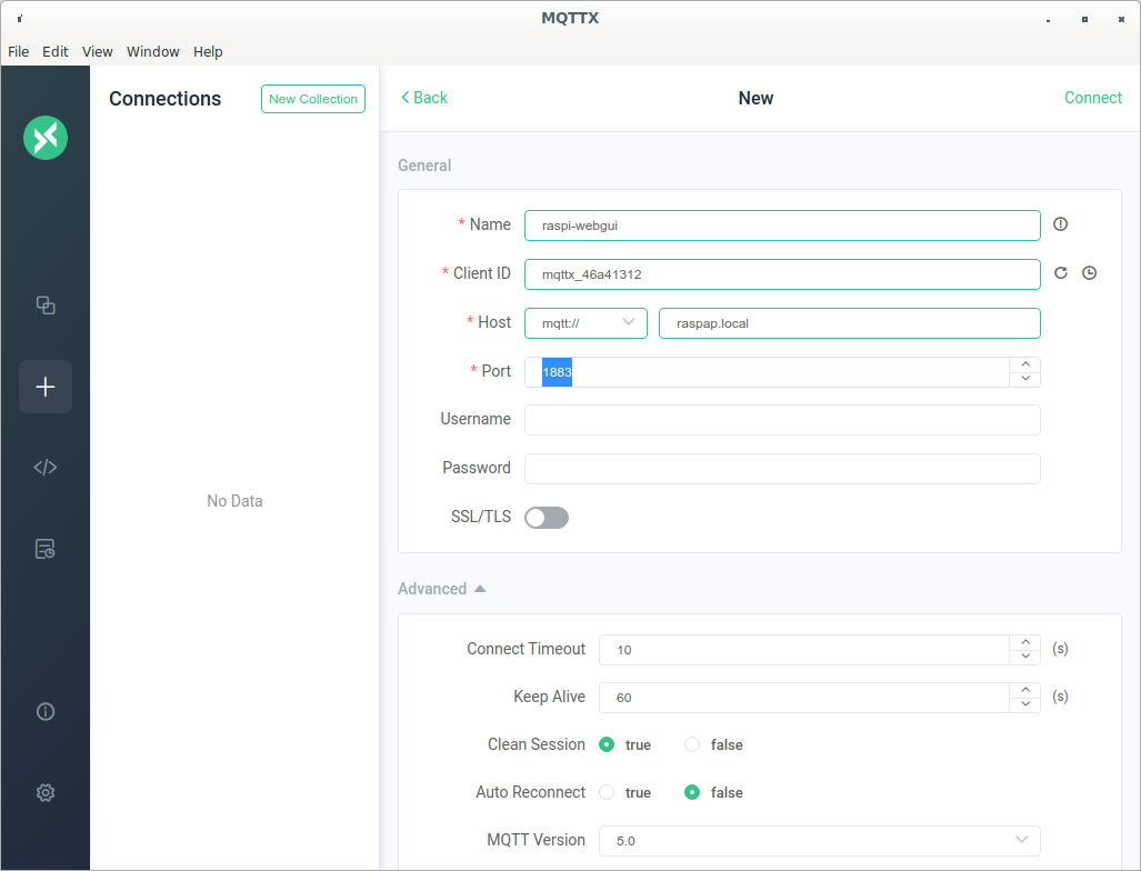
You now need the information of the MQTT broker that you want to subscribe to. Your instructor should provide you with the correct information. If you are using a local MQTT broker and Raspberry Pi access point your information will be something along the following lines:
- Name: raspi-webgui (this can be any name of your choosing)
- Client ID: mqttx_46a41312 (this will be different for everyone. You can leave it as is, or change it if you want.)
- Host mqtt:// raspap.local
- Port: 1883
Click on Connect in the top right hand corner of the
window. A small box should appear for a short while, saying
CONNECTED, after which the screen should look as
follows:
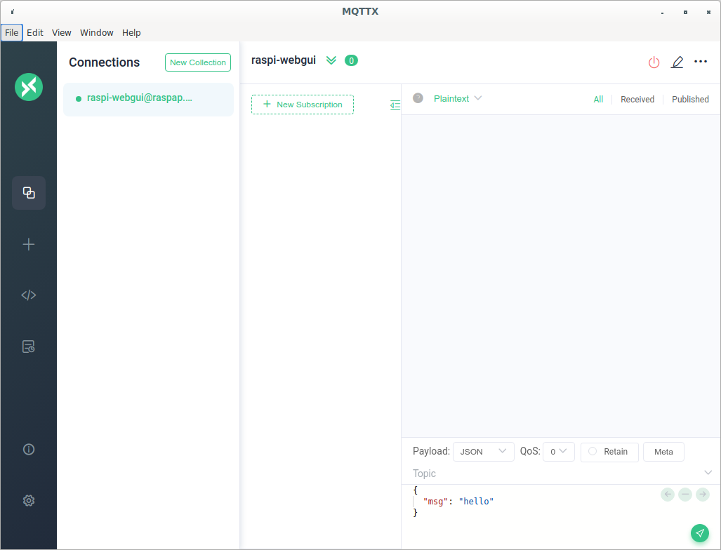
We are now connected to the MQTT broker and we can now subscribe to a topic.
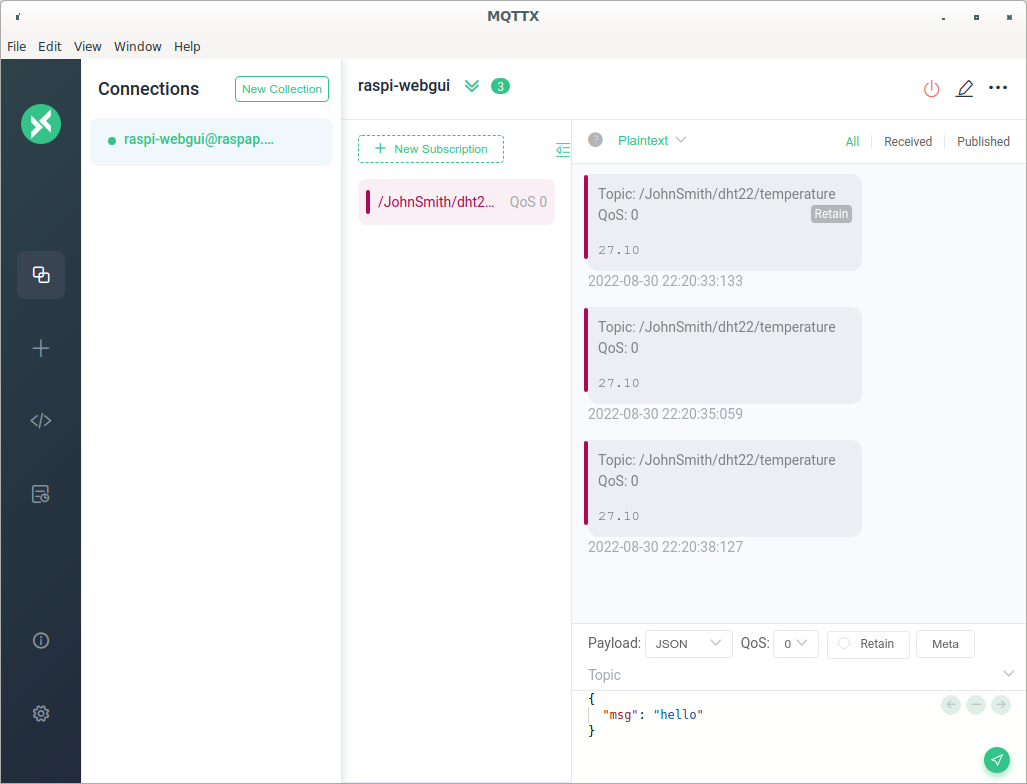
Click on th +New Subscription button. Enter
/JohnSmith/dht22/temperature (replacing JohnSmith with your
name as you entered it into the sketch) in the *Topic field
and click the Confirm button.
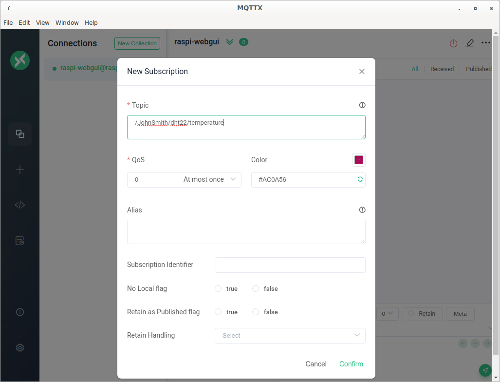
You should now see messages pop up showing the top and a value.
Challenge
Can you add a new subscription to subscribe to the light level that is being published from your ESP32?
Exporting data
MQTTX allows us to export the data that it receives to various formats. Allow MQTTX to run for a while to accumulate some data and then export the data to a JSON file. It is possible to export the data to a CSV but the format appears to be in a somewhat obscure format. It is possible to use convert the JSON to CSV using a converter such as the online converter that is available at www.convertcsv.com/json-to-csv.htm
- Use MQTTX to connect to a broker
- Subscribed to an MQTT topic
- Exported data to a file in JSON format