A very simple weather station
Overview
Teaching: 0 min
Exercises: 0 minQuestions
How to add a sensor to measure light with a Light Dependent Resistor (LDR)?
How to plot your data?
How to add a sensor to measure temperature with a thermistor?
Objectives
Become faimilar with the Arduino IDE development toolkit
Add a LDR to our circuit and get measurements
Make a plot with measurements
Add a thermistor into our circuit
Update our program to measure temperature
Write a program to measure light and temperature
Now that your Arduino Desktop IDE and Arduino Nano are both installed and working on your laptop, we can start to add an external sensor and control it via a program.
Using Input/Output on Arduino Nano
Before using an available Inputs/Outputs from our Arduino Nano board, let’s have a look at them:
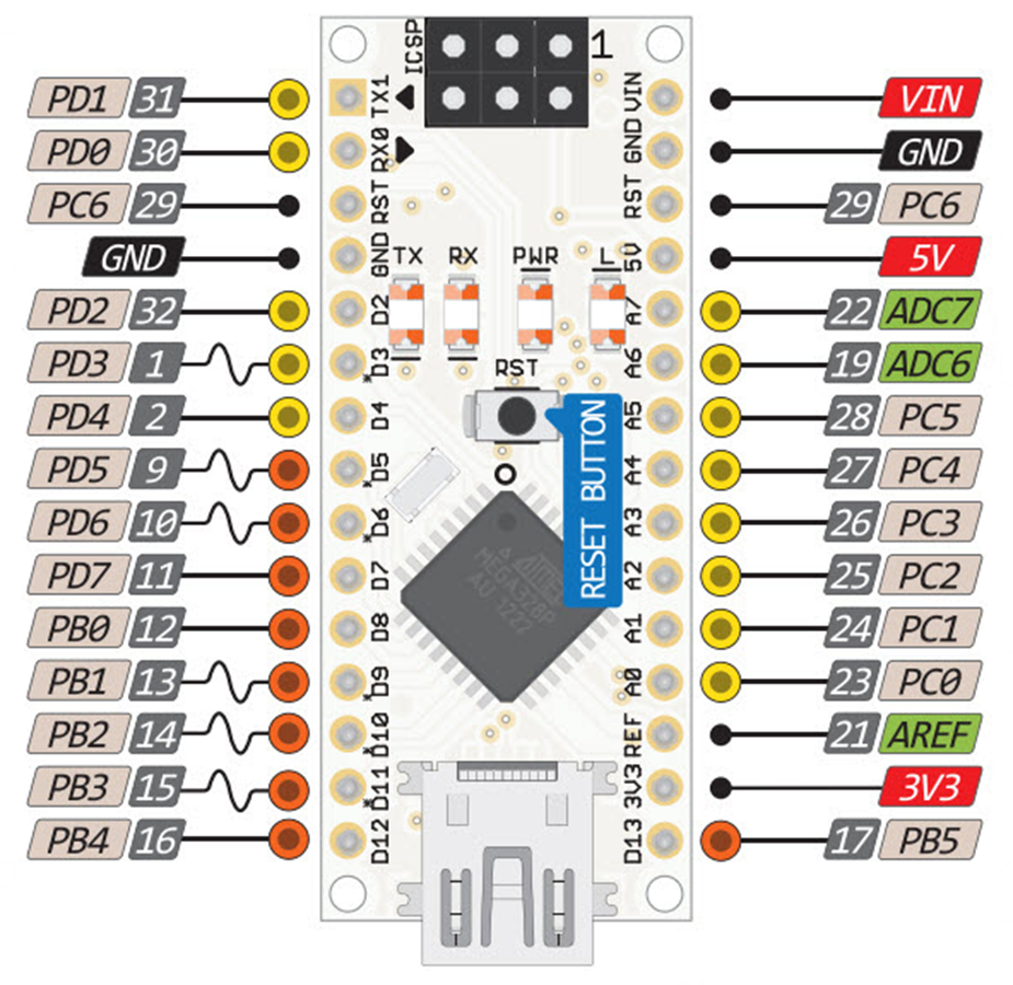
- Vin to supply power to the Arduino Nano (as a standalone device, without your laptop)
- GND Ground pins all connected together and serve as a 0V reference
- ADC Input for the built-in analog to digital convert
- AX are analog inputs and outputs pins
- DX are digital inputs and outputs pins (some of them can be modulated for outputs)
LDR
We will add a Light Dependent Resistor (LDR) to sense light levels, measure those levels with the Arduino Nano and print the measurements to the Serial port.
Arduino Nano measures Voltages on pins A0 to A5; but the LDR is a variable resistor (varying with Light). So we need to convert the varying resistance to a voltage that the Arduino iNano can measure.
We do that by using the LDR and a Resistor in a Potential Divider circuit.
Use the breadboard and the wires to connect the resistor, the LDR and the Arduino Nano together as follow:
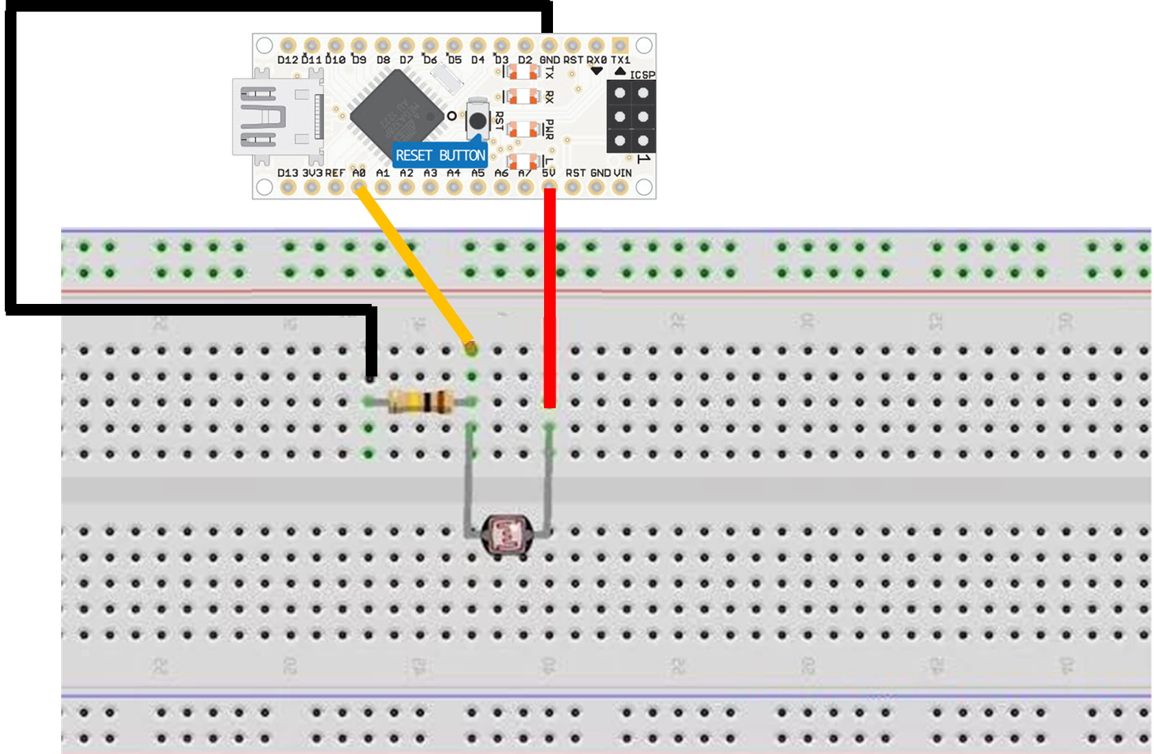
- Bend (gently) the 2 legs of the resistor (to make a U) and place it on the breadboard on two parallel rows;
One leg of the LDR is connected to VCC (5V) on the Arduino Nano, and the other to the analog pin 0 (A0) on the Arduino Nano. A 2.2 kOhm resistor is also connected to the same leg and grounded.
Tips for the breadboard
Breadboards consist of tiny “holes” in which the leads of the component connect into.
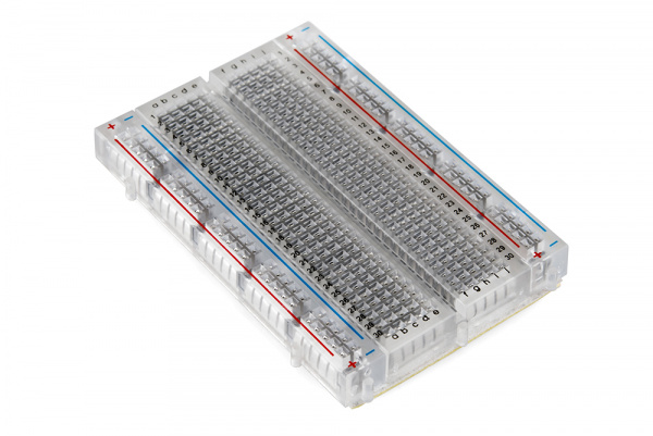
But holes are not all connected to each others.
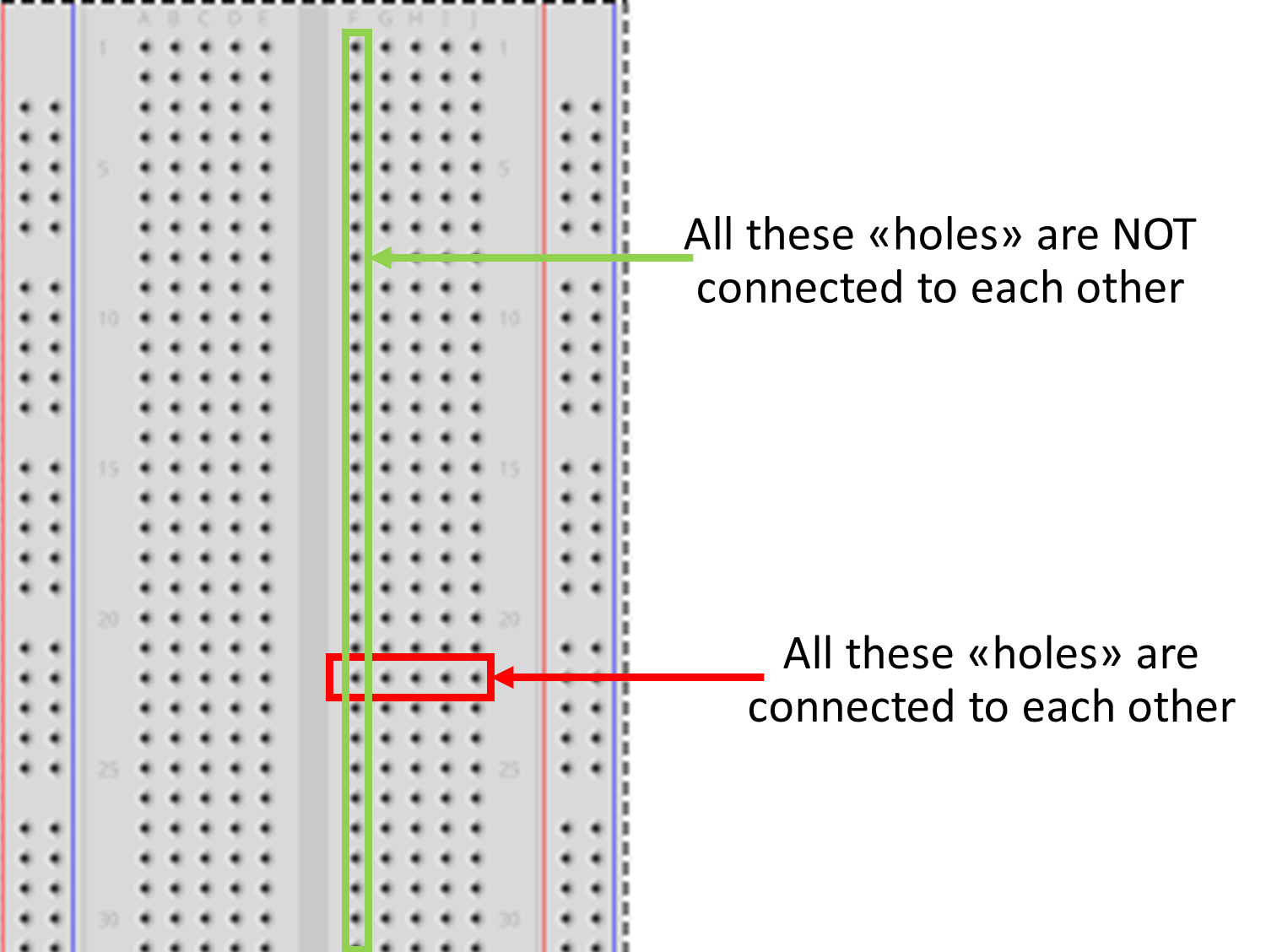
More information can be found here
Measure light levels with an Arduino Nano
Create a new sketch (New button) and paste the following code:
int sensorPin = A0; // select the input pin for LDR

int sensorValue = 0; // variable to store the value coming from the sensor

void setup() {
Serial.begin(9600); //sets serial port for communication
}

void loop() {
sensorValue = analogRead(sensorPin); // read the value from the sensor
Serial.println(sensorValue); //prints the values coming from the sensor on the screen

delay(100);

}
As before you can recognize the two main parts of the program:
- setup() that is run once only
- loop() that is run in loop (never stops).
To run it:
- Check your electronic circuit before running your programm.
- Connect your Arduino Nano to the USB port of your laptop
- Select Arduino Nano board (if not done yet) and the right USB port
- Upload program to the Arduino Nano
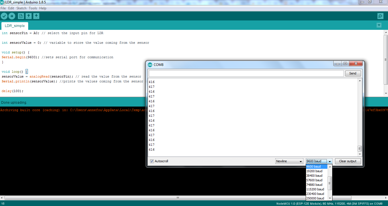
In the program above, we use a new built-in object called Serial to communicate with the serial port. We set its speed to 9600 baud (so you also need to adjust the speed of the serial port in the Arduino IDE).
To see the values written on the serial port, open the tab “Tools –> Serial Monitor”:
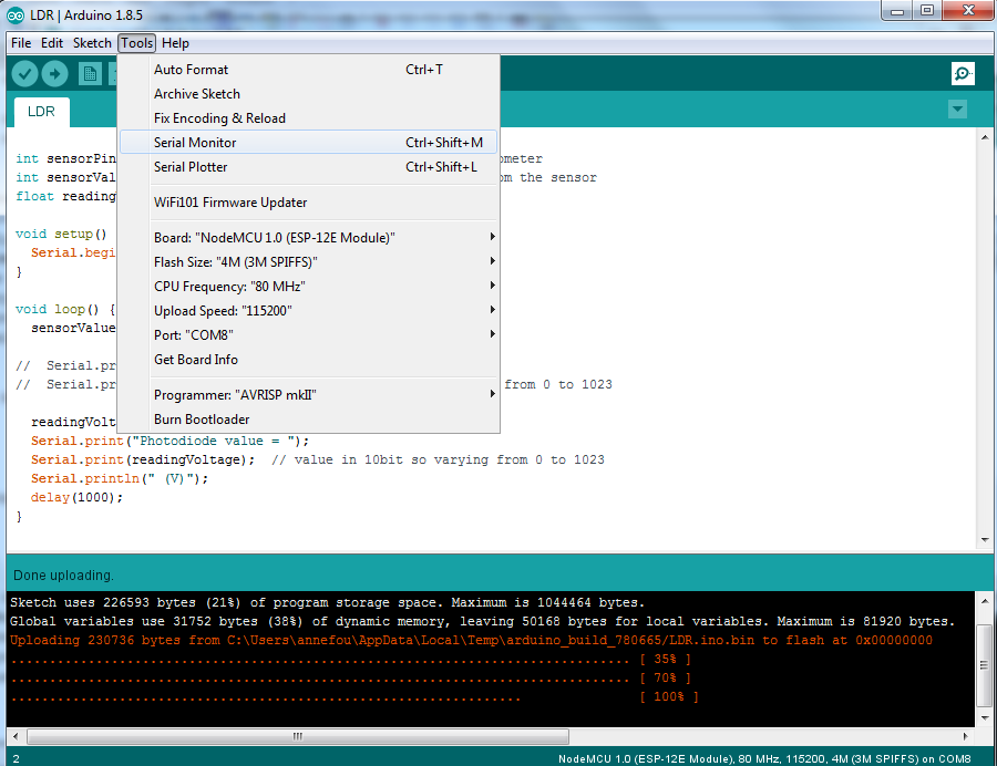
Then make sure, you set the speed of the serial port to 9600 (same value as in your program). You should then see the raw values printed in a this new window:
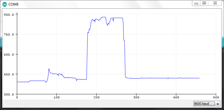
Make a plot
Close the Serial Monitor and then open the Serial Plotter (Tools –> Serial Plotter).
You should see a plot as shown below.
So far, we printed and plotted raw values only. We can scale these raw values:
int sensorPin = A0; // select the input pin for LDR

int sensorValue = 0; // variable to store the value coming from the sensor
float readingVoltage;


void setup() {
Serial.begin(9600); //sets serial port for communication
}

void loop() {
sensorValue = analogRead(sensorPin); // read the value from the sensor
readingVoltage = sensorValue* 3.3/1023; // we have 10 bits precision (1^10 = 1023)
                                        // and 3.3V as voltage input for analog to
					// digital convertor
Serial.println(readingVoltage); //prints the values coming from the sensor on the screen

delay(100);

}
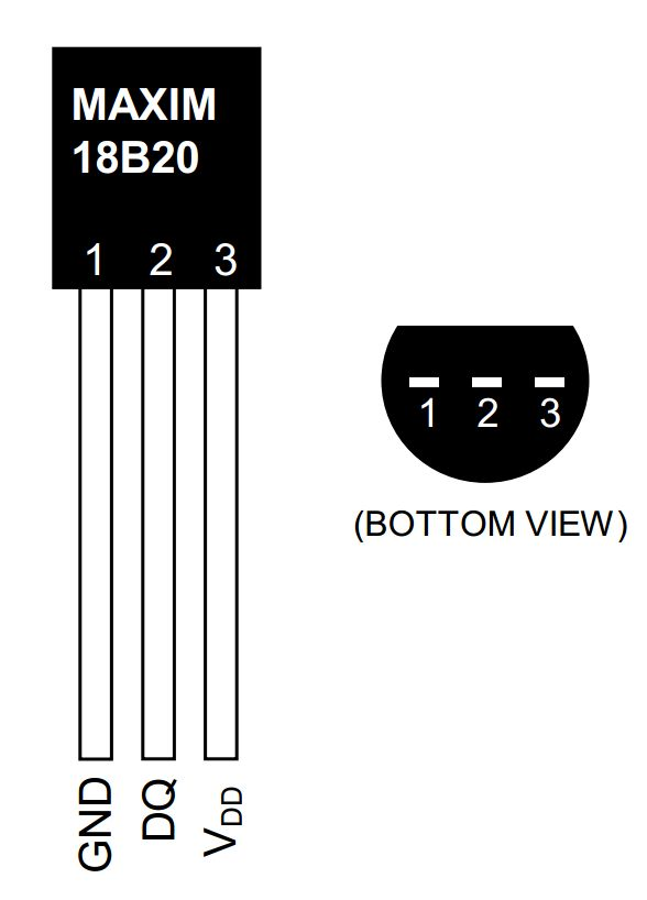
DS18b20 information
Connect a DS18b20 to our Arduino Nano
We will add our DS18b20 to the previous circuit. For now our LED will blink independently from our temperature sensor. Later, we will add a LDR and switch on the LED at “night”.
-
First disconnect your Arduino Nano from your computer
-
As for the LED, we need to add a resistor in order to pull down the voltage to 0 and allow the sensor to send a new value.
In our example, a 4.7 kohm will be used.
-
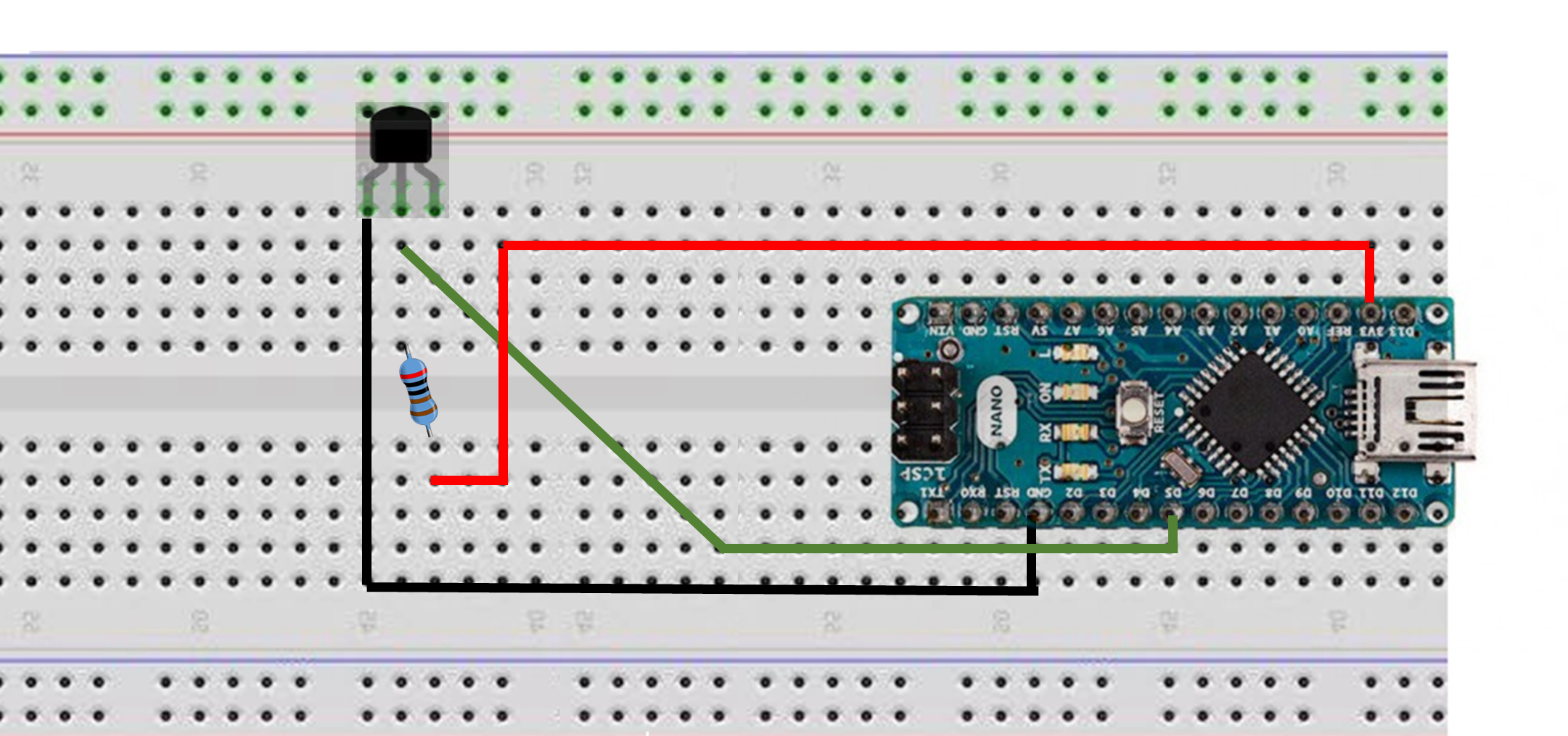
Bend (gently) the 2 legs of the resistor (to make a U) and place it on the breadboard with one leg connected to the second leg of the DS18b20 (DQ) and the other leg connected to the last leg of the DS18b20 (VDD).
-
Finally connect the first leg of the DS18b20 to the ground (G), the second to 3V and the last to D5 as shown on the figure below:
Get data from your program
In order to acquire data from the DS19b20, you need to install a new library called “OneWire” on your computer.
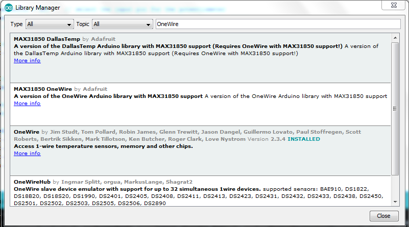
- Add OneWire to your Arduino libraries (Sketch –> Include Library –> Manage libraries)
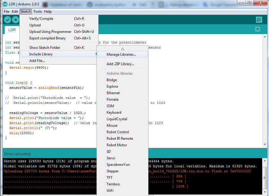
And then enter “OneWire” and install it as shown on the figure below:
-
Download the code to acquire and print data from the DS18b20 thermistor
-
Connect your Arduino Nano to an USB port on your computer. Check it is recognized properly.
-
Compile, upload and execute the code
#include <OneWire.h>

// OneWire DS18B20 Temperature Example
//
// http://www.pjrc.com/teensy/td_libs_OneWire.html
//
// The DallasTemperature library can do all this work for you!
// https://github.com/milesburton/Arduino-Temperature-Control-Library

OneWire  ds(5);  // on pin 5 (a 4.7K resistor is necessary)

void setup(void) {
  Serial.begin(9600);
}

void loop(void) {
  byte i;
  byte present = 0;
  byte type_s;
  byte data[12];
  byte addr[8];
  float celsius, fahrenheit;

  if ( !ds.search(addr)) {
    ds.reset_search();
    delay(250);
    return;
  }

  if (OneWire::crc8(addr, 7) != addr[7]) {
      Serial.println("CRC is not valid!");
      return;
  }
  Serial.println();

  // the first ROM byte indicates which chip
  switch (addr[0]) {
    case 0x28:
      //Serial.println("  Chip = DS18B20");
      type_s = 0;
      break;
    default:
      Serial.println("Device is not a DS18B20 device.");
      return;
  }

  ds.reset();
  ds.select(addr);
  ds.write(0x44, 1);        // start conversion, with parasite power on at the end

  delay(1000);     // maybe 750ms is enough, maybe not
  // we might do a ds.depower() here, but the reset will take care of it.

  present = ds.reset();
  ds.select(addr);
  ds.write(0xBE);         // Read Scratchpad

  for ( i = 0; i < 9; i++) {           // we need 9 bytes
    data[i] = ds.read();
    //Serial.print(data[i], HEX);
    //Serial.print(" ");
  }
  Serial.println();

  // Convert the data to actual temperature
  // because the result is a 16 bit signed integer, it should
  // be stored to an "int16_t" type, which is always 16 bits
  // even when compiled on a 32 bit processor.
  int16_t raw = (data[1] << 8) | data[0];
  if (type_s) {
    raw = raw << 3; // 9 bit resolution default
    if (data[7] == 0x10) {
      // "count remain" gives full 12 bit resolution
      raw = (raw & 0xFFF0) + 12 - data[6];
    }
  } else {
    byte cfg = (data[4] & 0x60);
    // at lower res, the low bits are undefined, so let's zero them
    if (cfg == 0x00) raw = raw & ~7;  // 9 bit resolution, 93.75 ms
    else if (cfg == 0x20) raw = raw & ~3; // 10 bit res, 187.5 ms
    else if (cfg == 0x40) raw = raw & ~1; // 11 bit res, 375 ms
    //// default is 12 bit resolution, 750 ms conversion time
  }
  celsius = (float)raw / 16.0;
  Serial.println(celsius);
}
Visualize data
- Tools –> Serial Monitor
It will show values as printed on a serial port in the program
- Tools –> Serial Plotter
It will plot the values. Please make sure you first close the Serial Monitor before opening the Serial Plotter (both cannot work together).
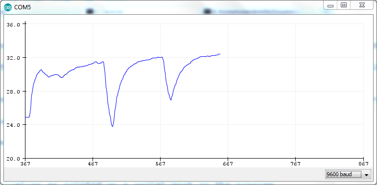
In both cases, make sure you select “9600 baud”.
Combine both the DLR and the thermistor
From the two previous program (DLR and thermistor), write a new program capable of measuring both the light levels and the temperature in degrees Celcius.
Hint: Reuse the two previous programs we have written.
Key Points
Use a motherboard with several sensors
Run our program to print and plot measured values